Showing posts with label Rhino3d. Show all posts

Tuesday, 5 March 2019

Faceted Brep Conversion for IFC

In Ifc2x3 data exchange, only a primitive model is required as the vast majority of implementations are developed with the use case of coordination in mind.   If a shape representation isn't an extrusion, then commonly it's meshed into faceted faces with 3 or 4 edges.  I'd really like to see revolutions used more commonly as the impact on many file sizes would be dramatic.

But a faceted brep can have any number of edges, and nominate internal bounds for openings.
Refer to this image and this description. 


We've been recently working pretty hard on ensuring that we can generate compact and efficient faceted breps from the accurate physical nurbs geometry in Rhino/Grasshopper so that a Building Information Model can also be provided within the IFC2x3 model schema.  We've decimated file sizes from the order of 200MB (when using the rhino mesher) to 30MB.  If IFC4 models could be used, there is an even more efficient polygonal faced representation or advanced breps could define the objects as IfcAdvancedBrep with nurbs faces and trims that could be roundtripped to Rhino.

Here's a grasshopper test case of the conversion.  You can access this if you update to the latest ggRhinoIFC plugins from the downloads page at www.geometrygym.com/


If you test on your own models and have any feedback, would be great to hear it.

Sunday, 27 September 2015

Geometry Gym Mac Plugins

It's a historic day, I've added a RhinoMac download area to the website, http://www.geometrygym.com/downloads


I believe these are the first plugins developed for RhinoMac, and it's an exciting new era.

Initially the two plugins available are BullAnt, and ggRhinoIFC (to import and export IFC files).

You need to install the WIP (Work in Progress) build of RhinoMac, you can download from here:
http://www.rhino3d.com/download/rhino-for-mac/5B/wip

Commands will then be available starting with gg (no toolbars yet).  You can open/import IFC files from the file menu.  You can run rhino command ggZZLicenseRequest to activate an evaluation license for the plugins.


Note that there are still improvements on the way (including features in RhinoMac) such as property panels .  I also plan to release mac versions of other utilities.  A lot of the other plugins I've developed for Rhino Windows probably aren't required on MAC as they link to Windows software.  Exceptions are the gbXML plugin and if you wish to see a build of another, then let me know.

I look forward to hearing feedback and suggestions.


Friday, 17 October 2014

Getting Geometry into Revit

I've been having a few requests recently about getting Rhino/Grasshopper geometry into Revit, and haven't really posted many examples of what is (and isn't) possible so thought I'd add some new examples to the blog.

Some of this functionality has been available a while, but I've refined it recently so update rhino and revit plugins from http://www.geometrygym.com/downloads

With the release of 2015, Revit has enabled some more generic solid generating functionality.
At the moment it enables plane faceted objects (with straight edges) and extrusions.  I've been putting forward requests for further improvements (including masking of internal edges with co-planar faces adjacent) and if more users do so, the faster we'll see this materialize.

Grasshopper is a fantastic tool for projects such as sports stadia, so here's a slightly simplistic example of generating some seating tiers.  You can use the IfcFacetedBrep shape representation with a categorization of an IfcSlab object (as a floor).  Here's an image of the resulting Revit import.  Note that it's not really possible to edit the object downstream (although I am working on improvements for updating the model).

It would also be really great to be able to fix walls to the underside of the objects.  To facilitate the ability to do something similar, it is possible to generate a revit extruded roof (subject to various constraints on what revit can do with this).  You'll find an example of this on the inner ledge.  Just note when using a stepped shape, you need to be careful that revit doesn't have thick roof types loaded in the project/template (but you need at least one).  Revit has a bug that crashes if the roof is generated with a proportionally thick type.  You can test with this blank project (download from here).  Here's the Grasshopper file (Rhino document units should be mm) and here's the resulting IFC file.

So this works for faceted objects with plane faces and straight edges.  If your shapes don't meet this criteria, one of the few options remaining for the time being is to import a SAT (or DWG) into a generic model family.  My tools can automate this process, allowing automation of categorization and assignment of parameters/properties.


Here's an example file to demonstrate this.  Rhino  Grasshopper (Grasshopper model with new Revit Components)  Note you can right click on the ggBake component and set the .SAT generation of IfcRepresentationMaps.  Also make sure you're using IFC4 if nurbs are applicable.  An IfcRepresentationMap is similar to a block in Rhino or a family symbol in Revit, ie a master geometry that is defined in the project/model as transformed instances.  Here's the resulting IFC file.


If you have suggestions for improvements, please let me know (enabling more categorization is on my todo list).  The more that also contact Autodesk asking for more and more functionality to generate geometric objects the more likely we'll see earlier implementations of improvements.

Thursday, 10 April 2014

gbXML for Rhino/Grasshopper

It's nice to be able to announce a new plugin I've been developing for Rhino v5 and Grasshopper to import/export Green Building XML ( gbXML) files.  Lots of aspects to implement and improve on, but I've advanced to a state where more public feedback and suggestions will help inform and shape this tool.
http://www.geometrygym.com/downloads

In rhino, the functionality is initially to import gbXML.  The identified data is arranged into a hierarchical layer with color contouring by zones and construction types.  There's also a tree viewer to inspect the gbXML entities and relationships.  If you select a node in the tree viewer, the associated rhino object will be selected.  Try rhino commands ggImportgbXML and gggbXMLTreeView


In Grasshopper, there are components to generate gbXML data in accordance with the schema.  Like the IFC plugin, this can be a bit intimidating to start, but should quite quickly become familiar.  To write out to file, for this plugin you select the gbXML generating component and bake this with conventional Grasshopper Bake icon.  Here's a sample grasshopper file generating some walls and openings.

As well as generating gbXML data, it is possible to interrogate, amend (and modify) existing gbXML files generated from other software.  The modifying components are hidden at this stage.  Grasshopper primarily duplicates data (with appropriate modifications) rather than modifying existing.  This makes data expiry (such as undo) quite difficult to implement which I still need to consider.  If you wish to access let me know.  Sample grasshopper file.


Thanks to Michal Dengusiak who has been instrumental in testing (and shaping) the tools thus far.  He's been testing the resulting data in TAS, who have also been generous in validating the generated gbXML and advising on technical aspects.  I look forward to getting feedback from other users interested in this.


Thursday, 23 May 2013

OpenBIM Scripting : Python IFC

Goswin posted to the Grasshopper forum a week or so ago about the possibility of scripting IFC data from Python (Rhino Python to be exact).  I hadn't had much of a chance to try Python to date, but I've tested GH Python today (Rhino python should work just the same).


You can download the sample GH def here.

Note there is also the possibility of using my c# libraries (from C#, VB.Net, Python or other compatible languages) outside of the Rhino/GH environment.  Get in touch if you would like to learn more.  Also not everything is enabled, but I can quickly do so.  Grasshopper is really a graphical programming language, so what is available there is certainly easy to provide in the API.

Sunday, 16 October 2011

IFC MEP and Reinforcement

A quick post to highlight recent improvements to importing MEP and reinfocement data from IFC files, as well as Grasshopper Generation of these items.  Still lots of improvements I'd like to make on this front, so please get in touch if you have particular requests.

Tuesday, 11 October 2011

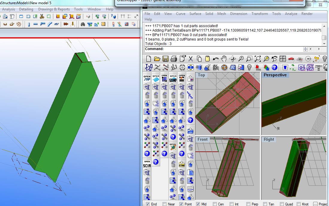
Rhino/Grasshopper to Tekla

In the past two months I have been progressing a Grasshopper plugin that enables direct exchange of data between Rhino/Grasshopper and Tekla.  Tekla is a quite compehensive BIM application, although I have initially concentrated on the structures aspect for Fabrication.


This has been driven by a couple of projects where the steel work has been modelled in Rhino to fabrication detail and precision, either by python scripting or manual modelling.  Rhino does not presently have direct extraction to NC format for fabrication, so a means to automatically extract this information from Tekla without duplicating modelling efforts has many benefits.

As part of this, I have been advancing some "reverse engineering" components to convert rhino polysurfaces (that do not contain "explicit history" information such as profile extrusion, end conditions such as miters or cut parts, or drilled hole locations.  This can be implied from the features that the polysurface (brep) has.


I still find Grasshopper a very convenient means to assign attributes such as steel grade, finish, part/assembly numbering etc, so the Tekla plugin is only a GH addon at this moment.  I am happy to assist with explaining/applying this tool to your project if it is of interest.

To download the installer, please visit http://www.geometrygym.com/downloads

As part of a presentation I will make later this week to the Light Weight Structures conference in Sydney, I prepared a grasshopper definition to emulate the primary structure of the velodrome (which owes a lot of it's success to the generative approach taken by all designers).


Here's another example model that you can try for yourself. Download


Monday, 15 November 2010

Grasshopper generating IFC Update

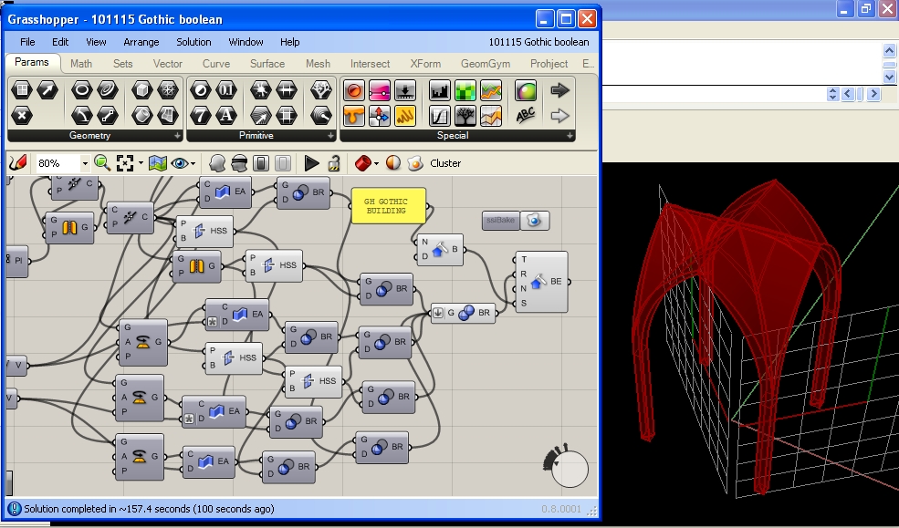
Thanks to Scott Davidson for the gothic inspiration and a great example of Grasshopper Generation and the ensuing improvements for exporting from Rhino/Grasshopper to IFC (can be imported by BIM software such as Revit, Archicad, Digital Project, Microstation, Tekla etc etc).

IFC2x4 is anticipated for formal release next year, which includes NURBS representations and should enable Rhino/Grasshopper models to be exported with greater accuracy and with greater ease.  Until then, IFC2x3 does provide means and ways to represent shapes and forms created by nurbs, and this blog post will demonstrate some of them.  Note most software does not recognize or work with all aspects of IFC, so approximations such as the first for faceting the brep may be your only option.

The first shape representation is using a faceted brep, effectively meshing the surface.  Unless your original shape is a faceted brep (with planar faces and straight edges), there will be a loss of detail, but you can control the refinement of the meshing process (introducing more faceted faces).


Grasshopper Definition    Generated IFC Data

Theoretically it's not necessary to approximate the form with a faceted brep if you can generate it using processes and shape representations within the IFC specification.  This includes extrusion and boolean operations which can be used to form this vault.  In practice, it seems very few BIM software and IFC viewers acknowledge or are capable of these operations, so you may be forced to use the faceting approximation.  Please test these models with your favorite IFC software and feel free to post your observations as comments.

Most programs comply with extrusion, here's Archicad importing this model:

Grasshopper Definition    Generated IFC Data

I've struggled to find even an IFC viewer to successfully display this model, but there's no warnings of non-compliance.  The boolean operations should work with a rhino model absolute tolerance set to 0.01


Grasshopper Definition    Generated IFC Data

Please post any comments with software you can or can't open these models with.  If you've any particular shapes you'd like to export that aren't successful, please get in touch and I can help advise.

Instructions for getting started with the IFC plugins are found here.

Sunday, 27 June 2010

ssiRhinoIFC Progress - Industry Foundation Class 2x3 - Import and Export

The first public alpha for ssiRhinoIFC is available for downloading at http://www.geometrygym.com/downloads  This allows importing, and some introductory exporting of IFC (Industry Foundation Class) version 2x3 for buildings and structure.

Whilst I'm the first to acknowledge there's a lot of work to be done to cover this comprehensive neutral BIM format, the basis of a very useful tool is already evident.  Working in a consultancy design office, we were often sent primitive DXF/DWG mesh models from steel detailers using software such as Tekla.  More intelligent models such as IFC will provide greater advantages for coordination and checking.

And IFC should also provide a very useful means of import/export to programs such as REVIT. An automated workflow from Grasshopper generation to external BIM software will reduce replicating work and coordination.

Development priority will be given to problems, suggestions, observations and ideas raised by users, so please download the plug-in, get the trial license and start exchanging IFC data with your other programs.

Start your testing by importing some of the example models I've been using, http://bimwiki.com/@api/deki/files/79/=NIST_IFC_Sample.zip and http://bimwiki.com/@api/deki/files/80/=Sample_IFC_files.zip contain a few model files to test.


And see if the IFC file exported from this Rhino model is compatible with IFC viewers and modifying software you use.  You need StructDrawRhino installed, use the command ssiIFCExport and select the beam centrelines.  You can move the locaction of the curves, apply different properties in the SDR property table etc.

A lot more to come on this in the near future, stay tuned....

Friday, 4 June 2010

David Rutten & Friends (AA London Lecture)

In front of a packed house, David Rutten, Daniel Piker and myself presented our recent work and developments for generative modelling utilizing Grasshopper3d.


You can view the presentation online at http://www.aaschool.ac.uk/VIDEO/lecture.php?ID=1212

David presented on his latest feature of Grasshopper, Galapagos (a genetic algorithm based solver).  It's fantastic how David can provide such an amazing user interface to the powerful tools he programs (When I was assisting Fred with the Genetic Algorithm solver for Naples, we had no time to program this visual feedback).

Daniel's work with Physics expressed in Kangaroo is amazing, and very popular.  It's going to be very exciting to see how designers utilize this into their design process.

And I presented on the Geometry Gym plug-ins featuring computation geometric design, and the existing and soon to be released BIM aspects of my tools.  It is becoming more and more apparent that if we have the power to generate many options rapidly, we need to ensure our evaluation tools (Such as structural analysis and other consultant design software) needs to be able to generated and evaluated quickly.  And there are massive benefits to minimizing coordination and duplicated model generation if we can transfer a Grasshopper model into BIM programs such as Tekla or REVIT (amongst many).  The Geometry Gym SDNF,  IFC (Industry Foundation Class) and CIS/2 tools are progressing rapidly.

Monday, 4 January 2010

Structure Analysis Model from Curves


Try for yourself the routines to generate structure analysis model from curves and points in Rhino.
Rhino Model from here.

Wednesday, 23 December 2009

Orienting Structure to Rhino Surfaces

Here's an example/tutorial for you to follow to use the plug-in to calculate member orientation angles based on the defining surface normal or nearest point.


To try this yourself, here is the Rhino file: Rhino Ellipse


Now the same basic procedure will work presently with 3 analysis packages, GSA, Sofistik (shown) and SAP2000. Strand7 and others coming shortly.
Here's the analysis models:
GSA
Sofistik (Note LOCA 0 is assumed for the moment.)
SAP2000

More instructions coming soon....

Tuesday, 1 December 2009

Weaire-Phelan intersecting a surface


I responded to a request for help on the Grasshopper forum with regards to generating Weire-Phelan polygons intersecting with a surface. I've recorded the screen capture below showing the difference as you halve the size of the polygons which I think is quite interesting. If you wish to try for yourself, the Rhino file can also be downloaded below, could be interesting to see how other shapes look (and to generate the intersecting curves using the command in the BullAnt plug-in)


Associated Rhino File

Sunday, 1 November 2009

British Museum Great Court Roof using StructDrawRhino

Another stunning, innovative structure that has inspired similar projects since.  It's a favorite space of mine, especially on a bright sunny day when the shadows and reflections are mesmerising.


Here's some papers, blog posts and links I found to determine how Happolds and Fosters designed this amazing roof.

http://opus.bath.ac.uk/14111/1/ChrisDeakin2001.pdf
http://www.enhsa.net/downloads/publi/con2004/102_Williams.pdf
http://people.bath.ac.uk/abscjkw/

So, now you can try to do something similar yourself using the structural plug-ins for Rhino.  My routines and commands don't follow exactly the description from the paper, but they allow something similar to be created.


To try this for yourself, the input Rhino file can be downloaded from here

I'm currently coding up algorithms for more powerful force density routines to include dynamic relaxation, but in the interim you can try the sdrMeshRepelVertex command to relax a rigid mesh outline with discontinuitys at nodes/vertices for continuing edges.  I used the sdrZigZagCurves command to divide the initial radial lines to generate the starting Grid.

From the starting flat grid, we can use the plug-in command sdrMeshProjectVerts to project the mesh vertices onto the mathematical surface.

Then we start the mesh relaxing process.  The command  sdrMeshRepelVerts uses force density to repel mesh vertex away from their neighbours.  Naked/Free edges/vertex will be restrained.  The more loops or iterations you allow, the better the result you will get.  Note that you can nominate a target surface that will vertically project the vertex back onto the surface (if you don't, the mesh will naturally flatten).  I found the best result was by nominating the balance force option for a number of iterations, and then to run a few loops of the target equal length for edges.

You can then extract the medge edges to curves using the sdrMeshDupEdges command.  By applying a structural profile (I assumed a much larger hollow profile than that used), the plug-in will automatically sweep the centreline curves.


There is also a number of routines in development for form finding and finding minimal surfaces.  Blog posts with worked examples will shortly follow, but if you look at sdrMinShapeMesh function you can try it for your self.  The other sdrMesh.... routines allow manipulation of mesh generated in Rhino to transform it to arrangements more appropriate for analysis/solving.

If you've any requests, ideas or suggestions for these routines (or need more help or other examples), don't hesitate to get in touch.

Monday, 17 August 2009

User Defined Profile Libraries

I've just uploaded a new version of the Structural Drawing Plug-in with plenty of improvements. I'm preparing to post a detailed tutorial showing how these new tools could be implemented to model the Beijing Water Cube, so watch this space.

The plug-in can now use profile libraries defined by the user. These are simply created by creating (or copying) rhino files into the plug-in sub-folder at C:\Documents and Settings\USER\Application Data\GeometryGym\UserProfiles\ or C:\Users\USER\Application Data\GeometryGym\UserProfiles\  (Note folder may be hidden, and is now reported on the Manage Tab of the main StructDrawRhino dialog). There's an example file there showing some numbers and letters as example profiles (you'll find them now listed in the selection drop down boxes). You can create as many collections of profiles as you like, and they will be grouped by filename (First Selection Box), layer name (Second Selection Box) and object name (Third selection box). The profiles must be located in the model YZ plane, and the origin is used as the default insertion point. A curve can be used to define a simple singular profile, or if it has voids, add it as a planar surface.


The files should allow easily to share and collate your profiles, let me know if you have any suggestions for improvements. Note that if you later rename either the file, layer or object, it will have to be reassigned. Another quick tip, the profiles are now assigned by dragging the first button over your model view (instead of clicking the button as per the previous release).

Sunday, 5 April 2009

More on Manipulating Structural Models

Here's the next entry with a tutorial/example on ways of manipulating your structural analysis model within Rhino.


It's been a month since my last post, but there's some great improvements on the way for the plug-ins, and you can see a sneak preview of some of this on the video clip for this tutorial.


Better quality AVI file for those that can't access YouTube or wish to see more detail.

In the current released version, when nodes are moved in the model, the centreline curves and 3d extrusions remain static to the old node positions.   To update the geometry, the nodes are updated in the GSA model, and then the existing Rhino representation must be manually replaced by running the interpreter command again.

The plug-in has now been developed with dynamically response to geometry manipulations made in rhino.  If you move or relocate nodes in the Rhino, the element centrelines (and shortly 3d extruded representations) will update on the new node positions.  Also the upcoming version will automatically replace/update any existing structural data in the rhino file, rather than require the user to manually delete it to avoid duplicate representation.

Anyway, here's some more methods/examples for manipulating your structural model node positions in Rhino.

This example is a simple representation of a bridge, for which we wish to investigate the form and shape.

GSA model: archBridge.gwb
Robot model: archBridge.str
SAP200 model : archBridge.s2k
Sofistik model: archBridge.dat
SpaceGASS : archBridge.txt
Strand7 model : archBridge.txt
And if you want the 3dm file with the parabola : archBridge.3dm

Open the GSA model, and copy all the GWA data from the gateway.
In rhino, right-click on the ggInterpretGWA button to generate the structural analysis model in Rhino (alternatively you can export the model to GWA from GSA, and left click to open the file).

We don't really need the 3d extrusions at this stage, so either untick the option, or turn off the layers once interpreted.

I'm going to use some point moving commands I've scripted into the latest version of the BullAnt plug-in which you can download from here: http://www.geometrygym.com/downloads  Note that most of the new commands and functionality being developed will only become active when you activate the free trial license for the plug-ins.
I hope to give some tutorials for creating your own RhinoScripts for some of these manipulations in the near future.
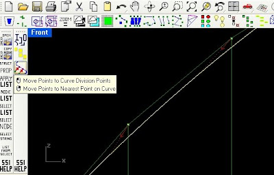


The first bulk node manipulation we're going to do, is to move the points to equidistant points on the parabolic curve which represents the arch shape we wish to assess and update our model.


In the BullAnt plug-in toolbar, there is a button for the command ggUtilMovePointsToCurve that will prompt the user for multiple points, and then a curve to move the points onto.  During the selection of the curve, the user may toggle whether end points on the curve should be included, and a tolerance for coincident points (useful if your model contains joints with coincident nodes).  The command will attempt to sort the points into a logical order, and then update each point position to the corresponding division point on the curve.  A confirmation step visually draws arrows and dotted lines representing the changes (you might have to zoom depending on the scale of the movements and overall selection).  Once updated (remember the present version of the plug-in won't update the element centerlines yet), you can copy the node coordinates to the clipboard, and then update your GSA model by pasting the GWA data to the gateway.

The video then shows the same sequence having scaled the parabolic shape to give it more height.

Note that the hangers are no longer vertical for our new profile.  If retaining vertical hangers is important, we'll use a slightly different , you can mov the vertical hangers in position so that they all interesect the desired parabolic curve.  I recommend changing the current layer to a new empty layer, so we can bulk select in a minute.  Then run the Rhino Intersect command to generate a point at all of the desired intersection locations.   We can then use the BullAnt plugin command ggUtilMatchClosestPoint to select an original and target set of points to match.  As the command can utilise a specified maximum distance to move any point, we can bulk select all the structural nodes by right-clicking on the "OasysGSA NODES" layer.  Confirm the selection (by enter or spacebar), and then similarly select the newly created intersection points in the second selection.  Every point in the first group within distance of a point in the second group will have it's position updated to the nearest, and we can update our analysis model.

Rhino allows so many methods and options of generating/updating point positions that you'll find you're only really restricted by your own experience or ability to learn new ones.  Many situations might require manual processing, others will allow techniques such as grasshopper, scripting and all tools and plug-ins available.  Some upcoming blog entries will look at these options.


Sunday, 22 February 2009

Geometry Gym Rhino Plug-ins


Geometry Gym (or SSI - Smart Structural Interpreter)

SSI is the beta branding for some Rhino plug-ins I've been developing for aprox. the past 12 months.

This project started as a response to various tasks and problems that I'd faced as an engineer working on projects of novel geometry.  Primarily this was difficulties in creating analysis models, checking analysis models were coordinated with project drawings, and for coordinating with other design team members, and in how to efficiently describe the geometry of these projects to other team members.  But the biggest problem was manipulating models to keep pace with project changes and evolution.  Although analysis software has made progress in this area, the methods were still largely manual and time consuming.  And part of the problem was that primarily all our drawings were done in 2D (plans, sections, elevations), and the CAD tools we used were focussed on this nature of drawing.

When I arrived in London and started work at Expedition I was introduced to Rhino3D, which is an amazing 3d modelling environment.  Rhino has many attributes that make it a fantastic tool for a designer, and I'll list a couple.  It can import and export so many CAD file formats (including Microstation and AutoCAD), it has an amazing support group of advanced users on it's newsgroup that will offer advice for everyone from beginner to expert, and for a scripter/programmer, it offers an excellent environment to allow automation and customization for generic and specific problems.

So the two initial plug-ins I've been developing for Rhino are an importer/exporter for structural analysis programs, and a catalouge structural section drawing tool.  I'll provide some instructions/examples for using these plug-ins in my following posts.  The importer/exporter allows automated drawing and updating of a 3d structural model without the need for manual interpretation and coordination.  It also provides advanced tools for efficiently manipulating and generating structural analysis data from within Rhino, so that analysis models can take advantage of the more sophisticated sculpting ability of Rhino than exists commonly in analysis programs.  The structural drawing plug-in is basically a sub-set (or by-product) of the first plug-in, that allows designers to manually extrude structural members, or easily add structural sections to rhino documents from a library of standard profiles.

Structural Modelling In Rhino3D

Here's some thoughts and opinions that I've formed in the 3 years I've been using Rhino to model structure and construction that might hopefully inform and assist any newer Rhino users reading this.  This is intended as a brief introduction to some of these topics, many of which I expect will form the basis of future posts.

COMMANDS
Many users like to operate Rhino primarily using the toolbars via their mouse, but of course commands can also be run from the menus, or by typing commands (or shortcut aliases) in the command window.  Primarily this is the way I work, and the blog posts will generally refer to commands by their command name (hopefully this allows readers to find references in help files easier), with some menu references.  If you're a convert from CAD programs such as AutoCAD or Microstation, you'll probably be reluctant to learn a whole new suite of commands (however similar they may be) for Rhino.  The good news is, you won't have to.  I would highly reccommend using an rhino alias to allow you to use command names/shortcuts that you are already familiar with, and most importantly allows you to use multiple cad environments simultaneously without frustration.  To do this, use the menu Tools-Options-RhinoOptions-Aliases.  A simple example is assigning an alias id to '_evaluatept 

TOLERANCE
Rhino commands and tools work to a tolerance that is specified by the user within each Rhino Document, and it's quite important that designers are aware of this and have given thought to the tolerance before they start modelling.  Problems due to a "loose" tolerance can emerge at later stage of project design, particularly when the model is used as an input to other uses such as rapid prototyping, or Finite Element Analysis.  I would highly recommend setting your tolerance as tight as you dare, and relaxing it when necessary if commands such as the boolean operations, intersection, splitting etc are failing.

The default tolerance is specified in your Rhino Template files.  Because Rhino is used in so many industries and purposes, the installed defaults should be edited for your purpose.  You can save your own defualts by opening a new document in your required units (ie metre, or milimetre etc), go to 

Here's the Rhino wiki entry on tolerance.

CONSTRUCTION PLANES AND MODEL 

It's common practise in CAD to model construction projects in worldwide position (ie OS coordinate system).  In Rhino, I'd strongly recommend keeping your model in space close to the origin by using a local project axes system.  You will likely observe display problems if you use a coordinate system with coordinates of a large value such as those typical in OS.  This is because Rhino uses numbers of "single" precision for display mesh positions.   But you can set up named construction planes (similar to User Coordinate Systems in  AutoCAD) that will enable you to interogate or specify coordinates in your model in large coordinate systems.