Sunday, 1 March 2009

Geometry Gym - Structural Analysis Data to/from Rhino

Geometry Gym has developed several plug-ins for Rhino that allows data to be transferred to and from Rhino from Structural Analysis programs used by Engineers to assess structural performance and strength.  This is currently released for Oasys GSA (which is used at our office at Expedition), and early versions are being worked on for other similar programs.

A lot of engineering time is spent on updating and altering structural analysis model geometry as projects and designs evolve and change.  Particularly when different design disciplines coordinate and accomodate to find efficient solutions.  By taking advantage of Rhino and using custom and default tools and commands, greater efficiency and productivity can be achieved in updating models.

You can watch this tutorial on this video link, then I'll explain the steps for you to try.

Initial GSA model here.
Initial Robot model here.
Initial SAP2000 model here.
Initial Sofistik model  here.
Initial SpaceGASS model here.
Initial Strand7 model here.


You can find the Rhino model with the a surface representing the desired shape here.

Download both these files to your computer.  Open the GSA model, but you can skip the step to export the model to GWA (text) format as the file is already supplied as such.  Note that all the nodes and elements lie on within a horizontal plane.

Open the Rhino model above, If you haven't already, install ssiGSA and then open the above rhino file.  Click on the import GWA button on the plug-in toolbar to import in the GSA model data.  Note that you can elect not to draw the 3d shapes for this example.

For this example, we want to move all the nodes in vertical location until they match the target surface.  This target surface was generated by the free Math Plug-in by Jess Maertterer.  

We can use the Rhino command project which will relocate objects perpendicular to the current cplane until they intersect with a target surface.  Only node data coordinates are sent back to GSA, so all the points can be selected by right clicking on the node layer.  Type in the Rhino command Project (ensuring you are in the Top view, or that a World Top Cplane is set in Perspective view), and select the surface as the target.  Ensure that the original data is deleted so that duplicate nodes are not present in the model.  You should see the planar nodes are now all lying on the surface.  The updated node coordinates can be obtained by clicking on the second button in the ssiGSA toolbar.  The GWA data will be copied to the clipboard, and can be imported into GSA by right clicking on the gateway and electing to paste data.  You can manually inspect the contents by pasting into WordPad (or similar text editior).  You will see the GSA nodes in their desired position.

Note this is one way of taking advantage of the advance sculpting and scripting environment of Rhino.  Upcoming blog entries will take a look at other simple but powerful ways of transforming models to efficiently change structure geometry.

Saturday, 28 February 2009

Geometry Gym-BullAnt

BullAnt is a plug-in that will be useful for CAD modellers, architects, engineers, and anyone developing Rhino models for construction projects that containing structural elements and representation.  The plug-in contains a library of catalogue sections, particularly hot-rolled and cold-formed steel sections available around the world.  This catalogue is still being developed so please forward any requests and suggestions through to me.

Here's some instructions to help with using the plug-in.

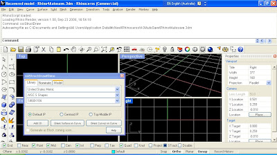
Once the installer has been downloaded and run on your computer, start Rhino and run the command ggStructDraw.  This will bring up the catalogue dialog (shown in the screen capture below) if it is not already visible.  This dialog can be docked in position, or float on your screen whereever is acceptable.

The radio buttons allow the user to specify the insertion point for the section, which will adjust how the section shape will relate to the points the user specified points when adding the structural shapes.  The default IP will generally match be the section centroid, except for asymetric shapes such as channels.  Top-Middle will orient the section shape below the insertion points.


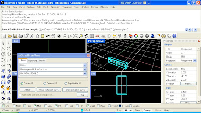
We will look at adding straight extruded sections initially.  By clicking on the Add 3D button, the plug-in command ggStructDrawElement is run.  The user can now select the first point defining the straight line along which the section will be extruded.


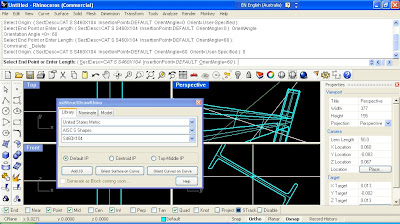
After selecting the first insertion point, the user is prompted for a second.  The length of the extrusion may be specifed by tpying in the number, and then the second selection point will specify the direction. Before specifying the end point of the extrusion, the user can specify if they wish to specify the section direction point, and the orientation angle in plane for the cross section to be rotated (in degrees).  By hitting ENTER when the command completes, it will be repeated.  If your desired section shape is replaced (at random) with the SSI logo, you either need to rerun the command, or request a free trial license for the plug-in by running the command  ggZZLicenseRequest .


Note in the plug-in dialog box, a Nominate tab is available as an alternative for the pull-down menus of the libary catalogue.  A description of the section shape can be entered as a string, in a format consistent with that adopted in Oasys GSA.  GSA contains a wizard for creating these shapes, here's an example : STD CH(m) 0.5 0.3 2.E-002 4.E-002  .  If you don't have GSA (a trial version can be downloaded), the online help describing this is here.

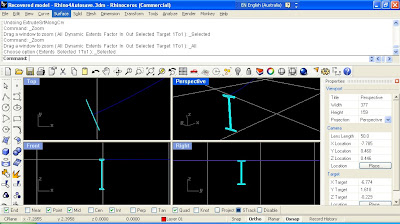
The plug-in also allows users to add a single face surface, or a perimeter curve of the section shape to the rhino document.  The command ggStructDrawSect will be executed from the other two buttons on the dialog, which will prompt the user to select an existing curve to orient the section shape on, and then for a point on that curve.  For this example I have sketched a free form curve, and have oriented a I shape on the start of the curve.

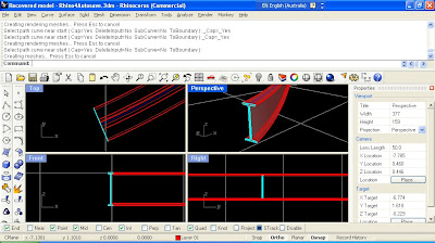
Once the section has been added to the document, it can be used as input to other Rhino commands.  For this example, I've extruded the surface along the curve by using the command ExtrudeSrfAlongCrv .  The images below show the solid resulting from this operation.

All suggestions for improvements for this plug-in gratefully received.  Current thoughts include allowing section specification consistent with other engineering programs, adding more sections (including other countries), and automating process such as section extrusion one existing curve.  Please let me know any other ideas and suggestions.

Sunday, 22 February 2009

Geometry Gym Rhino Plug-ins


Geometry Gym (or SSI - Smart Structural Interpreter)

SSI is the beta branding for some Rhino plug-ins I've been developing for aprox. the past 12 months.

This project started as a response to various tasks and problems that I'd faced as an engineer working on projects of novel geometry.  Primarily this was difficulties in creating analysis models, checking analysis models were coordinated with project drawings, and for coordinating with other design team members, and in how to efficiently describe the geometry of these projects to other team members.  But the biggest problem was manipulating models to keep pace with project changes and evolution.  Although analysis software has made progress in this area, the methods were still largely manual and time consuming.  And part of the problem was that primarily all our drawings were done in 2D (plans, sections, elevations), and the CAD tools we used were focussed on this nature of drawing.

When I arrived in London and started work at Expedition I was introduced to Rhino3D, which is an amazing 3d modelling environment.  Rhino has many attributes that make it a fantastic tool for a designer, and I'll list a couple.  It can import and export so many CAD file formats (including Microstation and AutoCAD), it has an amazing support group of advanced users on it's newsgroup that will offer advice for everyone from beginner to expert, and for a scripter/programmer, it offers an excellent environment to allow automation and customization for generic and specific problems.

So the two initial plug-ins I've been developing for Rhino are an importer/exporter for structural analysis programs, and a catalouge structural section drawing tool.  I'll provide some instructions/examples for using these plug-ins in my following posts.  The importer/exporter allows automated drawing and updating of a 3d structural model without the need for manual interpretation and coordination.  It also provides advanced tools for efficiently manipulating and generating structural analysis data from within Rhino, so that analysis models can take advantage of the more sophisticated sculpting ability of Rhino than exists commonly in analysis programs.  The structural drawing plug-in is basically a sub-set (or by-product) of the first plug-in, that allows designers to manually extrude structural members, or easily add structural sections to rhino documents from a library of standard profiles.

Structural Modelling In Rhino3D

Here's some thoughts and opinions that I've formed in the 3 years I've been using Rhino to model structure and construction that might hopefully inform and assist any newer Rhino users reading this.  This is intended as a brief introduction to some of these topics, many of which I expect will form the basis of future posts.

COMMANDS
Many users like to operate Rhino primarily using the toolbars via their mouse, but of course commands can also be run from the menus, or by typing commands (or shortcut aliases) in the command window.  Primarily this is the way I work, and the blog posts will generally refer to commands by their command name (hopefully this allows readers to find references in help files easier), with some menu references.  If you're a convert from CAD programs such as AutoCAD or Microstation, you'll probably be reluctant to learn a whole new suite of commands (however similar they may be) for Rhino.  The good news is, you won't have to.  I would highly reccommend using an rhino alias to allow you to use command names/shortcuts that you are already familiar with, and most importantly allows you to use multiple cad environments simultaneously without frustration.  To do this, use the menu Tools-Options-RhinoOptions-Aliases.  A simple example is assigning an alias id to '_evaluatept 

TOLERANCE
Rhino commands and tools work to a tolerance that is specified by the user within each Rhino Document, and it's quite important that designers are aware of this and have given thought to the tolerance before they start modelling.  Problems due to a "loose" tolerance can emerge at later stage of project design, particularly when the model is used as an input to other uses such as rapid prototyping, or Finite Element Analysis.  I would highly recommend setting your tolerance as tight as you dare, and relaxing it when necessary if commands such as the boolean operations, intersection, splitting etc are failing.

The default tolerance is specified in your Rhino Template files.  Because Rhino is used in so many industries and purposes, the installed defaults should be edited for your purpose.  You can save your own defualts by opening a new document in your required units (ie metre, or milimetre etc), go to 

Here's the Rhino wiki entry on tolerance.

CONSTRUCTION PLANES AND MODEL 

It's common practise in CAD to model construction projects in worldwide position (ie OS coordinate system).  In Rhino, I'd strongly recommend keeping your model in space close to the origin by using a local project axes system.  You will likely observe display problems if you use a coordinate system with coordinates of a large value such as those typical in OS.  This is because Rhino uses numbers of "single" precision for display mesh positions.   But you can set up named construction planes (similar to User Coordinate Systems in  AutoCAD) that will enable you to interogate or specify coordinates in your model in large coordinate systems.

Friday, 20 February 2009

Working effectively with geometry for Construction Projects

This is the first post (hopefully of many) that will provide tutorials, examples and provoke discussion for effectively generating, manipulating and assessing geometry for construction projects from stadia, to bridges, to buildings, to roofs, to anything else that is built.

It will primarily focus on using Rhino to effectively design construction projects, and explain how to take advantage of some tools I am developing, that utilise the amazing scultping and modelling environment within Rhino3d.  The plug-ins I am writing create efficient ways of drawing, generating and manipulating models representing structure, as well as exchanging the information back and forth with structural analysis packages.  I have set up a wiki for the plug-in, that can be found at http://ssi.wikidot.com 

I hope and encourage anyone reading these posts to contribute comments, suggestions, alternatives, and to request topics and tools for further development.  I'm expecting that the blog will cover all sorts of topics, from how to draw and model in Rhino, how to write your own RhinoScripts to Automate tasks, parametric modelling using Grasshopper, and we'll see what else. 

Cheers,

Jon