BullAnt is a plug-in that will be useful for CAD modellers, architects, engineers, and anyone developing Rhino models for construction projects that containing structural elements and representation. The plug-in contains a library of catalogue sections, particularly hot-rolled and cold-formed steel sections available around the world. This catalogue is still being developed so please forward any requests and suggestions through to me.
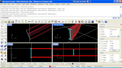
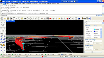
 Once the section has been added to the document, it can be used as input to other Rhino commands. For this example, I've extruded the surface along the curve by using the command ExtrudeSrfAlongCrv . The images below show the solid resulting from this operation.
Here's some instructions to help with using the plug-in.
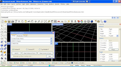
Once the installer has been downloaded and run on your computer, start Rhino and run the command ggStructDraw. This will bring up the catalogue dialog (shown in the screen capture below) if it is not already visible. This dialog can be docked in position, or float on your screen whereever is acceptable.
The radio buttons allow the user to specify the insertion point for the section, which will adjust how the section shape will relate to the points the user specified points when adding the structural shapes. The default IP will generally match be the section centroid, except for asymetric shapes such as channels. Top-Middle will orient the section shape below the insertion points.

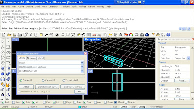
We will look at adding straight extruded sections initially. By clicking on the Add 3D button, the plug-in command ggStructDrawElement is run. The user can now select the first point defining the straight line along which the section will be extruded.

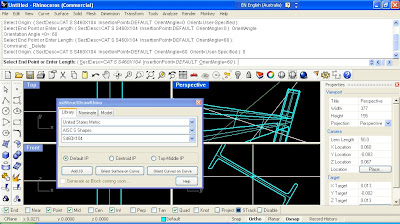
After selecting the first insertion point, the user is prompted for a second. The length of the extrusion may be specifed by tpying in the number, and then the second selection point will specify the direction. Before specifying the end point of the extrusion, the user can specify if they wish to specify the section direction point, and the orientation angle in plane for the cross section to be rotated (in degrees). By hitting ENTER when the command completes, it will be repeated. If your desired section shape is replaced (at random) with the SSI logo, you either need to rerun the command, or request a free trial license for the plug-in by running the command ggZZLicenseRequest .

Note in the plug-in dialog box, a Nominate tab is available as an alternative for the pull-down menus of the libary catalogue. A description of the section shape can be entered as a string, in a format consistent with that adopted in Oasys GSA. GSA contains a wizard for creating these shapes, here's an example : STD CH(m) 0.5 0.3 2.E-002 4.E-002 . If you don't have GSA (a trial version can be downloaded), the online help describing this is here.
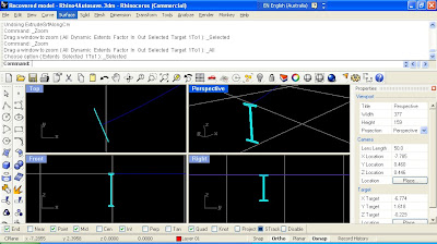
The plug-in also allows users to add a single face surface, or a perimeter curve of the section shape to the rhino document. The command ggStructDrawSect will be executed from the other two buttons on the dialog, which will prompt the user to select an existing curve to orient the section shape on, and then for a point on that curve. For this example I have sketched a free form curve, and have oriented a I shape on the start of the curve.
 Once the section has been added to the document, it can be used as input to other Rhino commands. For this example, I've extruded the surface along the curve by using the command ExtrudeSrfAlongCrv . The images below show the solid resulting from this operation.

All suggestions for improvements for this plug-in gratefully received. Current thoughts include allowing section specification consistent with other engineering programs, adding more sections (including other countries), and automating process such as section extrusion one existing curve. Please let me know any other ideas and suggestions.


Looks really great! Cant wait to test it out.
ReplyDeletecan you work on something for bolted connections? that would be another direction that SSI could develop towards..
ReplyDelete